Turn signal lamp function is to provide cues to the vehicle in front, behind or on the side that the bike will turn left or right or move the path. Turn signal system consists of the main components, namely two pairs of lights, a flasher / turn signal relay, and three-way switch (turn signal light switch three-way).
Turn signal flasher is a device which causes the turn signal lights winking in the interval / fixed intervals of between between 60 and 120 times per minute. There are several types of flasher, including; 1) flasher with a capacitor, 2) with a bimetal flasher, and 3) the transistor flasher.
a. Turn Signs Systems by Type Capacitor Flasher
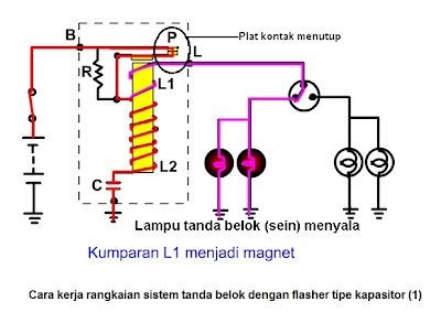
Example circuit with the turn signal flasher system type capacitors as shown below:

By the time the ignition is connected, but the turn signal switch is in position "off", current flows through the contact plate to L2 P then charge the capacitor. After the turn signal switch is routed to one of the lights, then the current also flows into the L1 continues to turn signal lights so that the lights on. Currently L1 be a magnet see the image below:
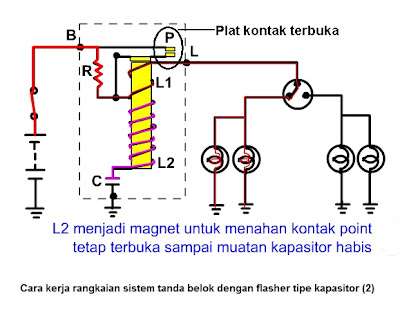
Shortly after becoming a magnet coils L1, contact plate (contact point) P is open, so that the current flowing into a small light as it passes through the fixed contact plate R. prisoners in open conditions for coil L2 is still a magnet provided by the capacitor to charge in a capacitor discharged see the image below:
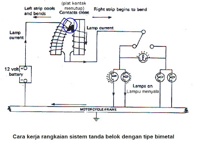
b. Turn Signs Systems by Type Bimetal Flasher
This type of turn signal system by relying on the work of two pieces / bar (strip) bimetal to control the blinking of lights. Bimetal consists of two different metal (usually brass and steel) are merged into one. If there is heat from the incoming power to the bimetal, there will be a development / expansion of the different metals with different speeds. This will cause the bimetal tend to be bent to one side. In type flasher bimetal bimetallic there are two pieces are mounted close together and each one has a contact plate at one end.
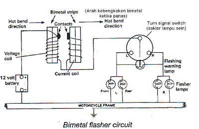
The way the system works with the turn signal flasher type bimetallic At the turn signal switch is moved (left or right), current flows to the coil voltage (coil) which will make the coil heats up and bent. After crooked \ her to connect the second contact plate at the edges, then the flow of current to flow to the coil (coil current) continues to turn signal / turn signal and finally to the masses (pictured below). Currently the turn signal is on and current will begin to bend away from the coil voltage coil.
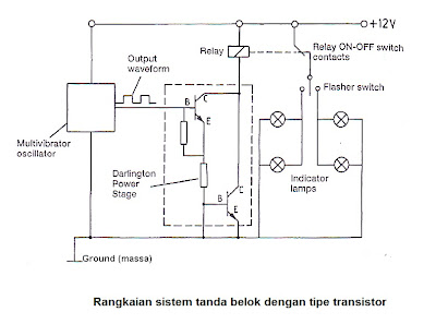
c. Turn sign system with flasher TipeTransistor
System with the turn signal flasher flasher using transistors that control the type of mechanical contacts can not anymore, but already electronically. This system uses a multivibrator oscillator to generate pulses (pulses) ON-OFF which will then be directed to the flasher (turn signal relay) melawati amplifier (power amplifier). Furthermore flasher would switch off the lights so that the lights turn signal is flashing.